|
Planning a trip to Sicily? Then,
make sure you won't be feeding the Mafia!
 |
|
|
If you have a scientific interest in the physics of the
radio, you should browse this site as an e-book!
|
|
|
|
ERRANTE's BALUN
Virtual ground balun for
dipole & loop
A state-of-the-art high power
broadband HF balun
|
|
Patent n.0001347484
(ITAPA20030019) and
Patent n.0001347486 (ITAPA20030021)
Visit the European Patent Office to see all the patents of mine
HERE
!
|
|
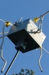
Errante's 50/70 Ohm virtual ground balun
Freq. range: from 1 to 30 MHz
RF Power: 2KW CW
Click on the thumbnails to view larger
pictures
|
|
N.B. The balun pictured above is
available as standard for the following impedance values:
NEW! unbalanced 50 Ohm
input to a 225+225 Ohm balanced output to suit the Errante's 225 Ohm,
multiband HF antenna system ;
unbalanced 50 Ohm input to a 70 Ohm balanced output to suit an ½
wavelength open dipole antenna;
unbalanced 50 Ohm input to a 300 Ohm balanced output to suit an ½
wavelength folded dipole antenna;
unbalanced 50 Ohm input to a 50 Ohm balanced output to suit an ½
wavelength inverted Vee dipole antenna;
unbalanced 50 Ohm input to a 200 Ohm balanced output to suit a full
wavelength, single turn, Deltaloop antenna.
Any other impedance values combination to be manufactured upon special
order.
|
|
ERRANTE's
BALUN : what it is, how it works and how it came to be
made.
by Francesco Errante
The virtual ground balun presented hereby is the practical
application in the field of the short wave radio communications of what the
Author has previously created for scientific purposes. It, infact, along with
the virtual ground balun for doubling the ½
wavelength folded dipole antenna, descends from the radio-electric circuitry for the suppression of
anyone of the two branches of a ½ of wavelength open dipole.
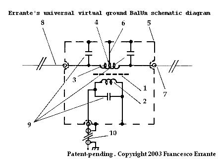
Errante's balun is, essentially, a pure electrical transformer
which, in its most elementary layout, has a minimum of 3 tuned circuits: a
primary circuit (primary winding LC network) and 2 secondary circuits
(secondary windings LC networks).
Generally, the Errante's balun secondary circuits are identical to
each other in order to feed symmetrical balanced antennas. When necessary,
the secondary windings can be formed to have impedance values different
between each other, while maintaining the phase angle difference of the
balanced terminations to a constant ±90 degree with respect to the virtual
ground node. Moreover, as all the pure electrical transformers,
Errante's balun can be made to have more than a couple of secondary
windings.
Errante's balun is characterized for NON allowing any
impedance transformation to take place unless its terminations impedance
values are matched (NON-fluctuating impedance).
Errante's balun terminations impedance values are set by design,
hence the impedance transformation ratio is a function of them and not
viceversa, unlike it happens with any other balun arrangement. See
for example the Guanella's or the Ruthroff's
transformers which are instead characterized by having a fluctuating
terminations impedance values, as they are nothing else than an arrangement
of auto-transformers, their input and output circuits are unseparable and,
therefore, any change made to their primary circuits will inevitably affect
their secondary circuits.
In practice, a balun having a fluctuating termination impedance value carries
out its impedance transformation duty within a very ample range of impedance
values, changing its input termination impedance according to the one of its
load and viceversa. Therefore, supposed we have a Guanella's type
balun with a transformation ratio of 4:1, it will show an input impedance of
75 Ohm if its load impedance is of 300 Ohm, or it will show an input
impedance of 50 Ohm if its load impedance is of 200 Ohm. This cannot
happen if an Errante's type of balun is employed, because each
termination impedance value is a fixed property of the relevant termination
and does not vary even if there is a change in the values of the impedance of
the circuits (antennas or transmission lines) connected to them.
By limiting the line-load system impedance to the imposed values only, it is
possible to inhibit both lines and loads (antennas) from giving origins to
unwanted resonances, which are, generally, harmonic resonances, very often
deriving from the presence of more than a load on the same feed-point, which
generates alternative paths for the RF. (for example: multiple
dipoles o monopoles, fan antennas and so on). This is something not
to be underestimated, not only with regard to the transmitting phase but and
above all, to the receiving phase as well. Employing a NON-fluctuating
impedance balun, infact, introduces a very high rejection to interfering
radio signals from sources outside the bands of the radio spectrum for which
an antenna is ment. This translates in an excellent stability and selectivity
of the transmission line or antenna systems which employ Errante's
baluns.
A virtual ground balun represents the ideal device for the correct feeding of
dipole and loop antennas. The virtual ground balun carries out many functions
at once allowing to:
1) match the RF source impedance to the chosen load while introducing
neglectable insertion loss of power;
2) transform the RF signal fed to it into two identical portions with the
correct phase angle difference for the natural feeding of open or folded
dipoles and loop antennas;
3) obtain a virtual ground node for the correct polarization of its
unbalanced port;
4) obtain a common ground path for the dissipation of the charges induced by
the electrostatic phenomena;
5) obtain an high de-coupling between its two balanced ports.
The generic virtual ground balun's schematic diagram is shown here below.
|
The virtual ground balun is housed inside a
weatherproof rugged metal enclosure having two separate compartments: one
hosts the balun circuitry while the other one protects the coaxial
connectors. The said metal enclosure not only ensures an high mechanical
robustness and a total stability against the weather agents, it also works as
the general electric conductor for all the references to the virtual ground
node. Such an enclosure ensures also a full electrostatic shielding of the RF
balun transformer circuitry.
Radiondistics claims the originality of the balun's unique
electromechanical layout, as well as the balun radio-electric
circuitry.
Operational advantages:
|
a. the virtual ground balun allows the feeding of
dipole and loop antennas with much less loss than conventional
baluns
b. the virtual ground balun allows an aerial to exhibit a much larger
bandwidth compared to when the same antenna is fed by a conventional
balun.
c. the virtual ground balun allows an antenna to exhibit a much
stronger immunity to parasitic capacitive effects compared to when the
same antenna is fed by conventional baluns.
d. the virtual ground balun allows an antenna to exhibit a strong
resonance stability, regardless of the level and inclination of it
above the ground.
e. the virtual ground balun allows an antenna to exhibit a much
stronger immunity to out-of-band emissions compared to when the same
aerial is fed by a conventional balun.
f. the virtual ground balun allows an antenna to exhibit a much
stronger immunity to electrostatic charges and noises compared to when
it is fed by a conventional balun.
g. the virtual ground balun, owing to the constructive and destructive interference
phenomena taking place in the transformer allows the dipole antenna to exhibit a sharper
radiation/reception pattern (off the beam axis signal rejection) compared
to the same aerial when fed by a conventional balun.
h. the virtual ground balun allows a much faster antenna deployment
time compared to conventional baluns.
i. the virtual ground balun allows an antenna to exhibit a much better
compatibility with highly populated environments (EMC TVI) compared to
when it is fed by a conventional baluns.
|
Applications:
|
a. SHORT WAVES FIXED & MOBILE RADIO STATION FOR
CIVIL & MILITARY PURPOSES
b. STEALTH, FAST & TACTICAL DEPLOYMENT PURPOSES
c. SEARCH & RESCUE SERVICES
d. SHIP to SHIP & SHIP to SHORE MARINE COMMUNICATIONS
e. DX-ing and metropolitan HAM RADIO STATIONS
f. ELEMENT in ARRAYS of AERIALS
g. RADIO-PHYSICS LABORATORIES
see also SWR-metered
balun
|

Prices:
Euro 250,00 +V.A.T. and shipping costs.
N.B. The price of the new 50/225+225 is Euro 500,00 +V.A.T. and shipping
costs.
For an useful currency converter click here
RADIONDISTICS' products carry an unconditional lifetime
guarantee.
|
|
|
|
Schematic diagram of
Guanella's and Ruthroff's baluns
|
|
|
|
|
|
|
All the concepts, methods, designs and devices presented on this
web site
are the original novelty works of FRANCESCO ERRANTE.
Patents & Copyright © 1985- of FRANCESCO ERRANTE.
Material is governed by the Copyright, Designs and Patent Act.
No reproduction, in whole or in part, without written permission.
Copies of these documents made by electronic or mechanical means, including information storage and retrieval systems, may only be employed for personal use.
All rights reserved.

|
All rights reserved. Copyright © 1985- Francesco Errante
www.Radiondistics.com - Tel.(+39) 339.180.1313
|
|